The XL1 card also only recognizes Longword (32 bit) transfers and
ignores all word and Byte transfers by requiring Longword,
DS0, and
DS1 to be asserted and A<1> = 0![]() at the beginning of any valid
at the beginning of any valid ![]() read or write cycle. DTACK will not be returned
and there should be a timeout in any other case. The address bits above
A<1> are then used, in conjunction with the AM decode, to
map into FEC memory and register space. If the MVME167 SBC, the
Bit3 Nubus
read or write cycle. DTACK will not be returned
and there should be a timeout in any other case. The address bits above
A<1> are then used, in conjunction with the AM decode, to
map into FEC memory and register space. If the MVME167 SBC, the
Bit3 Nubus VME bus extender,
and the VME bus extension hardware were
capable of cleanly addressing all of the available address space
A<31..2> then no further requirements would need to be imposed.
However, the MVME167 and the Bit3 crate to crate interface cards
used in the back end of the system require that significant
regions of the A<31..2> (1GW) address space be set aside.
Since a simple flat memory map for SNO with 20 crates of 16
cards with 1MW each would require 5 (1/32 crates) + 4 (1/16 cards -
ignoring trigger etc.) + 20 (1MW) bits or 29 out of the 30 available
bits, some other more complex mapping scheme must be employed.
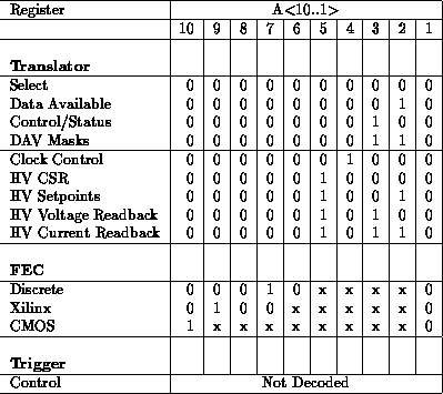
The scheme that we have settled on is to have one level of indirection - a register in the bottom of the register space that selects which of the 18 boards in a crate (16 FEC + Trigger + Translator) is to be addressed in any instruction. This effectively removes 4 address bits from contention and allows us to use any 5 bits in the 10 bit range A<31..22> (memory address space - AM=09) to identify a crate. This does, however, mean that we need a register to select the board of interest and we need a place in register space to put that select register. The solution to this is to set up the FECs and the Translator (XL2) cards with overlapping register spaces. The bottom four registers in the crate are always the registers physically located in the Translator (XL2) that control and monitor this board selection process. The global register allocation for the Translator and FECs is shown in the following table:

At the moment the upper Translator registers (Clock and HV) require that the Translator card be specifically selected - i.e. that bit 17 of the Select Register (A=0) is set. This is to allow some growth in FEC register space and to require an additional explicit action in order to play with clock or HV parameters - this requirement should be examined for rationality by the SNO-CAT group. One should also note that the Trigger card has cheaped out and does not do any decoding of the address lines as it has only one miserable register at the moment so any reference to the Trigger Card register space addresses the same place. The FEC registers are discussed at length elsewhere.
Another point to note is that the master may, at its discretion, set more than one bit at a time in the Select Register. This is, of course, quite confusing during normal data reading and should be avoided, but was included because it greatly simplifies system startup and some diagnostics. The simplification comes about because of the great similarity of the initialization patterns FEC to FEC. For instance, the four Xilinx chips on each FEC are configured after power up by loading a bit stream from the master. Since the total length of the bitstream is nearly 1/4 Mbit, it is clearly a savings in time to simultaneously load all FECs with this identical data. Similarly many of the DAC settings are likely to be identical and might reasonably profit from simultaneous loads. Care should be taken, however, in using this feature and we should consider whether we wish to incorporate any hardware checks or safeguards against multiple selects during normal operation (at the moment there are no hardware checks).