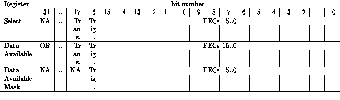
The High Voltage Bus is physically separate from the SNObus (to prevent arc-over or leakage) but in the J2 region vertically. The HV bus is mounted on standoffs from the SNObus and is connected only to the 16 High Voltage Cards via a small four pin connector (High Voltage, High Voltage Return, Interlock In, and Interlock Out). There is a jumper field at each location to connect the HVC to either HV supply A or supply B (this is necessary because, in a small number of cases, crates of tubes can not be arranged to run within a hundred volts or so of each other). As in the case of the crate geographic address, this connectivity (to A or to B) is known ahead of time and the HVA Supply and HVA Return lines (or B as the case may be) will be hard jumpered on the backplane. The interlock lines are a simple jumper from HVC to HVC and a complete circuit serves as an indication that all HVCs are properly seated and that the HV power may be applied. At the moment the design calls for an open interlock chain to prevent a high voltage relay from closing and prevents the actual application of HV power to the PMTs. It is possible that it would be preferable to implement this function in software.
whimper