The Barrel and End Cap electrical and electronic designs are identical, but mechanical differences in the detailed construction of the detectors and geometric differences in the straw density (the Barrel has a straw about every 40 mm2 while the End Cap Wheel A has a straw about every 80 mm2) make the printed circuit board solutions for the two cases very different. The main design responsibility for the End Cap case is now at CERN (started at Penn) and the main design responsibility for the Barrel case is at Lund, but Penn is actively engaged in kibbitzing and testing both versions. The main End Cap test system is located at CERN, the main Barrel test system is now coming together at Penn.
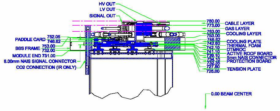
on two circuit boards near the top - the two boards are connected by miniature multi contact connectors, indicated as yellow blocks in the drawing. Shown below are photographs of a complete 64 channel board set - the board on the left is the innermost board and holds eight ASDBLR chips plus input protection diodes and resistors. The ASDBLR outputs flow through the connector to the second (middle) board which has four DTMROC chips mounted on it. The right hand board is a cable connector that brings in power, clock, and data and takes out the high speed data stream. (no cables are attached in the photograph.

For more details on the End Cap, check out the CERN
TRT pages and Peter Lichard's
pages.
For a discussion of some of the Barrel issues (as of January 2001), see the note by Bjorn Lundberg.
For a summary of the brainstorming discussion held at
Penn Feb 1-2 2001, see here.
Note that this includes a discussion of the height of a possible two or
three board stack for the Barrel.
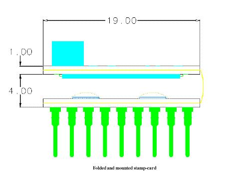
Cartoon sketch of a stamp flex board - the yellow line indicates
the flexible (Kapton) signal connection between the ASDBLR and DTMROC sections
of the board.
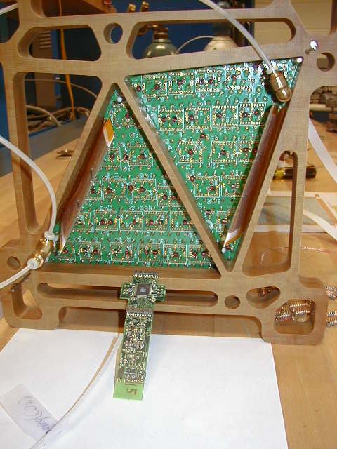
For a better sense of scale, one can see the end of module 2.1 (a 520 straw module assembled at Duke) in the following picture. The small cruciform board is a test device (TB3) that has two ASDBLRs and one DTMROC mounted, but in an extended fashion to allow easy probing and diagnosis. The Kapton plates on the left and right of the photo are the HV connections to the cathodes. A small "Fuse Box" brings HV in and distributes it to the multiple loads through individual custom fuses. The brown structure is a life size replica of the eventual space frame that holds the modules (and the barrel SCT and Pixel detectors).
 For
more pictures in this series.
For
more pictures in this series.
For more details on the Barrel module mechanical design,
check out the Indiana
and Duke sites.
-----> On Board Chip Bar Code Matrix reading.
Directory of images, code, and readme files.
Readme files in .doc and .pdf format.
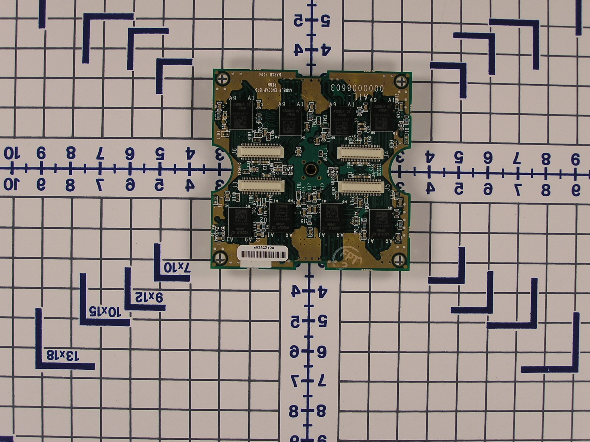
a type A Wheel Board photo (note that this photo needs a threshold of about 20)
and, in zip files....
Some images.
Code package.
 Last Modified - October 2003 FMN